26 Mar
2026
Energeks

The power industry loves paradoxes.
The largest devices in the power system very often depend on the smallest details. A transformer can weigh several tonnes, have a rating of several hundred kilovolt-amperes and run without a break for 30 years. And yet the spot that often decides its reliability is only a few centimetres in size.
It is the transformer clamp.
More precisely, the LV clamp that connects the low voltage cables to the stud of the LV bushing of an MV/LV transformer.
To someone outside the industry it looks like an ordinary piece of metal with a few screws. A detail hardly anyone notices as long as everything works.
For a power engineer it is a completely different story. It is one of the most critical points of the whole installation. This is where high currents, mechanical forces from heavy cables, temperature changes and a very practical question meet: will this connection safely survive years of work in real conditions?
LV transformer clamps are screwed onto the threaded studs of the LV bushings. They take the conductors of the cables running to the LV switchgear, increase the contact surface and improve the mechanical stability of the connection.
This brings very concrete benefits.
Lower contact resistance.
Lower risk of connection overheating.
More predictable transformer operation over a long service life.
That is why grid operator standards, for example the TAURON 5/2014 standard used by a Polish distribution system operator, specify LV clamps without crimped cable lugs, and why we supply TOC-1 transformer clamps and TOC-2 for MarkoEco2 oil transformers. They are not an aesthetic detail or a marketing add-on. They are a solution born from a very practical need: to better control current, temperature and connection mechanics in a place that looks unremarkable but matters enormously in practice.
This article is about exactly those issues.
We will show what LV transformer clamps are and how they are built.
We will look at why a cable bolted directly to the bushing stud can be problematic.
We will explain how the clamp design affects current, temperature and contact resistance.
We will also see why grid operators require stable connection solutions and clamp covers.
And we will show, with examples, in which installations transformer clamps become fundamental to the reliability of the whole substation.
Reading time: approx. 10 minutes
Anyone who has ever stood next to an open MV/LV transformer knows that moment.
You look at a massive machine. Several tonnes of steel, a magnetic core, oil, windings. Everything looks calm, heavy, almost majestic.
Then your eyes stop on something the size of a hand.
The clamp.
And this is where real engineering begins.
Because this is not an ordinary piece of metal. On a 630 kVA transformer, each LV phase clamp carries about 900 A at full load. The clamp must carry this current flawlessly, withstand temperature changes, vibration and mechanical forces from the cables, and keep a very low contact resistance for years.
A transformer clamp works like an adapter between two worlds.
On one side there is the transformer and its LV bushing, the point where energy leaves the tank.
On the other side there are the LV cables, often two per phase, thick, heavy and not very flexible.
The clamp adds a conducting element between them. In TOC clamps it is a tin-plated brass forging with stainless steel fixing screws and brass pressure screws. This element increases the contact area, stabilises the conductor and spreads mechanical forces over a larger area.
From the point of view of physics, three important things happen here.
The current has a larger surface to flow through.
The metal to metal pressure is more even.
The connection is less sensitive to movement and stress.
The effect is simple. Less heat, fewer problems, more peace of mind in operation.
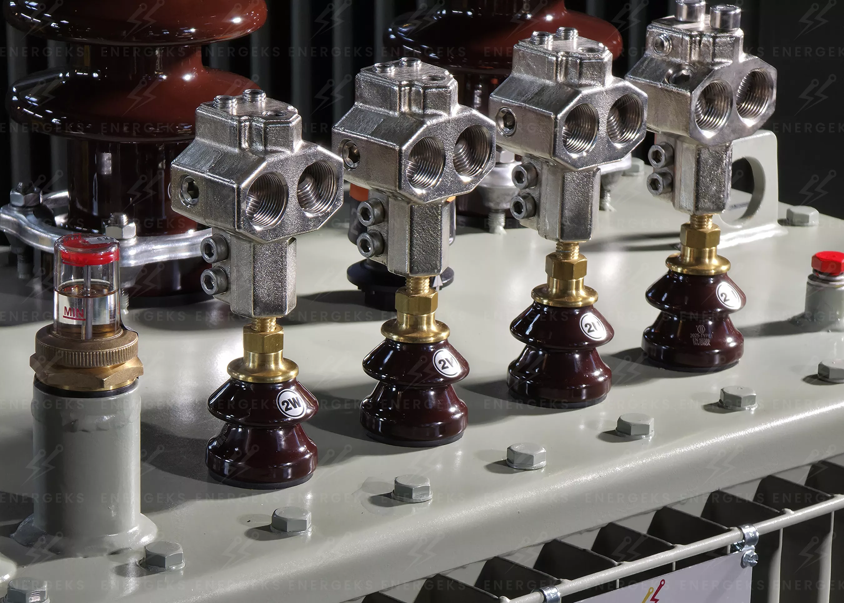
The photo shows TOC-1 transformer clamps mounted on the LV bushings of a MarkoEco2 oil transformer. Each clamp takes the conductors of LV cables without crimped lugs, and its solid body increases the contact surface and lets the current flow evenly. At the same time the clamp takes part of the mechanical load from the heavy cables. This inconspicuous spot is where current, temperature and connection durability meet, and they must stay stable for decades of operation.
Photo: Energeks 2026
A cable lug, a bolt, tighten it and done.
In theory it works perfectly.
In reality three very concrete problems appear.
The first is the weight and stiffness of the cable.
LV cables with large cross-sections, for example 240 or 300 mm², are not delicate. They are heavy, springy structures that very often do not want to go exactly where the design intended. If the cable arrives at an angle or under tension, it starts working like a lever and loads the bushing stud.
The second problem is the contact surface.
Metal never touches metal perfectly. Current flows through microscopic contact points. If there are few of them, the current density rises, and the temperature rises with it.
Suddenly a small resistance turns into a local source of heat.
The third problem is time.
A transformer does not work in ideal conditions. There is vibration, temperature change, thermal expansion of materials and short overloads. If the connection relies on a single pressure point, micro-movements can appear over time.
And micro-movements have a bad reputation in the power industry. Because they almost always end with a worse contact.
That is why the TAURON 5/2014 standard (point 6.10.8) specifies LV clamps without crimped lugs, in a cable or busbar version, as a set of three phase clamps and one neutral clamp.
But even then the story does not end. Once the mechanics and the electrics of the connection are sorted out, the next level of challenges appears: the transformer works in the real world, not in a laboratory. In a substation, in an environment full of moisture, dust, changing temperatures and uninvited biological activity that the power industry knows only too well.
At first glance they look a bit like small black hoods.
And that is exactly why they are easy to underestimate. Someone looks at a transformer, sees bushings, clamps, porcelain and metal, and treats the covers as an extra.
Yet in the power industry such small things very often do the dirty work that lets everything else run quietly.
The cover is put on the LV clamp after the cables are connected. It covers live parts in a place where the distances between phases are small. In other words, exactly where we do not want to leave anything to chance, weather and the creativity of nature.
They are most often described as protection against birds and rodents. And this is not an industry legend. Animals really can cause trouble in a transformer substation. It is enough for them to get close to two points at different potentials, and physics immediately takes over. A short circuit occurs, the protection trips and suddenly there is an outage nobody planned.
The role of the cover is simple: to make accidental contact with live parts harder and to reduce the risk that something or someone bridges two potentials. A bird, a small animal, a branch, a metal object, and sometimes even a tool during service work.
A cover does not make the transformer armoured. But it very effectively limits the risk of the simplest, most absurd and unfortunately quite real events. The kind after which you look at the report and think: really? because of that?
That is why the TAURON 5/2014 standard (point 6.10.14c) requires LV clamp covers made of a self-extinguishing, flexible material. The OZNN cover is made of flexible self-extinguishing rubber, comes in three sizes, M12, M20 and M30, and fits TOC-1, TOC-2 and MK 1 clamps.
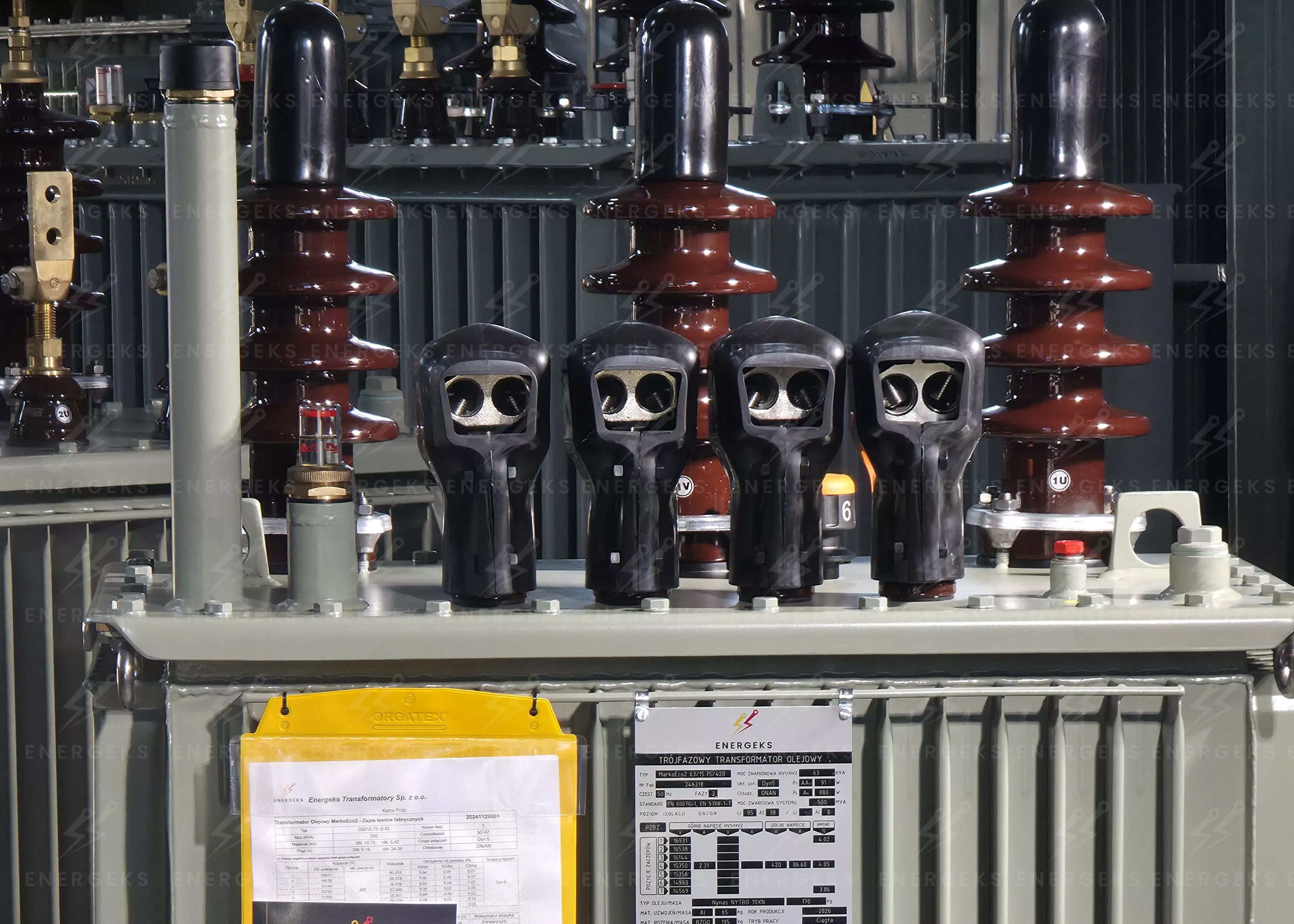
The photo shows an Energeks oil transformer with LV clamps hidden under black clamp covers; MV bushings in the background. The covers protect the clamps against accidental contact with live parts and reduce the risk of short circuits caused by birds, small animals and other external factors.
Photo: Energeks 2026
From the design point of view, it makes most sense to choose the whole connection system as one coherent solution instead of putting it together later from random parts: transformer, clamps and covers. Such sets are available from Energeks, and the easiest way to agree the configuration is to contact us directly.
This is the part of the power industry that looks unremarkable from the outside and is pure physics on the inside.
At first glance a transformer clamp is simply a metal part that connects a cable to the transformer. But the current does not flow evenly through the whole contact surface. It flows through the places where metal really touches metal, and there are far fewer of those contact points than intuition suggests.
That is exactly why the clamp design matters so much.
If the contact surface is larger and the pressure more even, there are more real contact points. That lowers the contact resistance. And lower resistance means less heat where we least want to see it.
The power lost in a connection is P = I² × R. At a current of about 900 A, every additional 0.1 mΩ of contact resistance means about 81 W of continuous heating in a single clamp. A hot contact oxidises faster, its resistance rises further and the process feeds itself. More on this in our article why transformer clamps overheat.
A transformer clamp does three important things at once.
First, it increases the contact area, so the current has more room to flow calmly.
Second, it spreads the pressure better, so the connection does not rely on one small piece of metal.
Third, it keeps everything stable over time, so the risk of micro-movements that can degrade the contact over the years goes down.
You can compare it to road traffic. The same number of cars squeezed into one narrow street quickly creates chaos. Given a wide road, everything flows much more smoothly. Current behaves in a similar way.
The range of cross-sections matters too. TOC clamps take two main conductors per phase, 2 × 95 to 240 mm² (RE, RM, SM) or 2 × 300 mm² RMC, plus two auxiliary conductors of 2 × 2.5 to 50 mm², with aluminium or copper conductors. The thread and current are chosen according to the transformer rating: M12 (250 A) up to 160 kVA, M20 (630 A) for 250 and 400 kVA, M30 (1000 A) for 630 kVA. Details in our guide how to choose a transformer clamp.
Grid operators have one big advantage over the rest of the market. They do not see a single transformer, they see the whole recurring picture of operation.
For a designer, a transformer is a device matched to technical parameters. For an investor, it is part of a bigger puzzle. For a grid operator, it is part of a system that has to run quietly not for a year or two, but for decades.
When you look at thousands of units working in different locations and under different loads, you quickly see which solutions age well and which only look good on the day of acceptance.
That is why operators look not only at the transformer rating, the loss level or the insulation parameters, but also at how the LV cable connections are made. Is the connection mechanically stable? Is the contact surface sufficient? Does the system cope well with stress from heavy cables, vibration and temperature changes?
In many cases the transformer itself works flawlessly as a machine. The windings are in good condition, the oil keeps its parameters, the core runs steadily. The problem starts where it meets the outside world. Exactly where the cable connects to the transformer.
This logic is behind the operators' technical requirements: LV clamps without crimped lugs, a set of three phase clamps and one neutral clamp, covers made of self-extinguishing material. Some operators, for example the Polish DSO Energa-Operator, also require that a 25 × 4 mm earthing strip can be connected to the neutral clamp. The /N versions of TOC clamps allow this.
Because in the end the operator does not buy just a transformer. The operator buys peace of mind in operation.
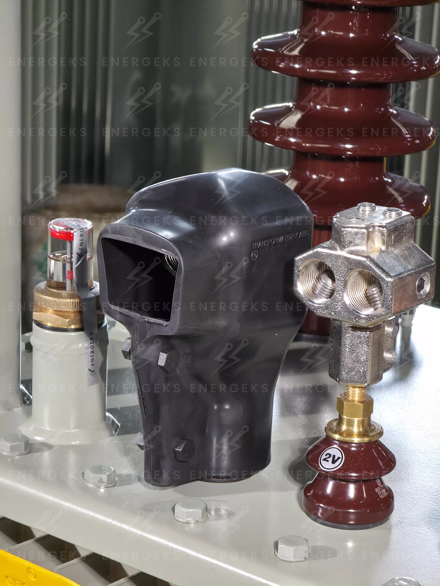
The photo shows a TOC-1 transformer clamp on an LV bushing and, next to it, an LV clamp cover that is put on after the cables are connected. Clamp, bushing and cover must be chosen consciously and work as one coherent system: reliability starts with the detail.
Photo: Energeks 2026
There are installations where a transformer has a fairly comfortable life. It runs steadily, the cable arrives without acrobatics, and the load does not ride a rollercoaster every day.
But there are also places where reality quickly checks whether the connection at the transformer was designed with care or only so that it could be bolted together and the job closed.
Take photovoltaic farms. The transformer works there in conditions that like to test the patience of materials. In the morning the power rises, then comes full sun, a cloud, sun again, and the ambient temperature does its part. Current and temperature change dynamically, and every such cycle means work for the material, the pressure and the contact.
It is very similar in industrial installations, except that here there is often a process on the other end of the cable that really does not like downtime. If the connection at the transformer starts to heat up or lose stability, it is no longer a minor technical flaw. It is the beginning of a problem that can affect the whole site.
Then there are compact substations, where theory very quickly meets cramped reality. The cables come in from below, the switchgear is close by, and the LV bushings have their spacing. Where there is little room on the cover, the compact TOC-2 clamp works well: sockets in one compact head, a split shank and locking screws on the side. Where the cables are thick and need to be led out comfortably, the standard is TOC-1 with its offset foot. We describe the differences in our article types of transformer clamps.
Because the truth is quite simple. A transformer can be excellent, and the whole majesty of several tonnes of equipment is still put to the test by a few centimetres of metal at the connection point.
Related topics worth knowing:
Why do MV transformer bushing terminals have one or two mounting holes?
How to choose a transformer clamp? M12, M20 or M30
Why do transformer clamps overheat? Installing and inspecting LV connections
Types of transformer clamps: cable, busbar, neutral and MV bushing clamps
Theory is theory and physics is physics, but in the end someone simply has to close the topic. The transformer, the clamps and the covers have to be chosen so that everything fits together not only in the catalogue, but also in a real substation, with a real cable and the real requirements of the grid operator.
That is why it makes most sense to think about them together. Energeks offers low-loss MarkoEco2 oil transformers and, for them, TOC-1 clamps, TOC-2 clamps in /U phase and /N neutral versions, and OZNN covers. We match TOC clamps to MarkoEco2 transformers.
To choose clamps and covers for a specific project, write to us. That way the whole system can be matched to the cable routing, the installation conditions and the requirements of the site.
If you like technical stories from the power industry told without pomposity but with respect for detail, follow us on LinkedIn.
Sources:
PN-EN 60947-7-1, the standard referred to in the TOC clamp data sheets.
TAURON 5/2014 standard for MV/LV transformers, points 6.10.8 (LV clamps) and 6.10.14c (LV clamp covers).
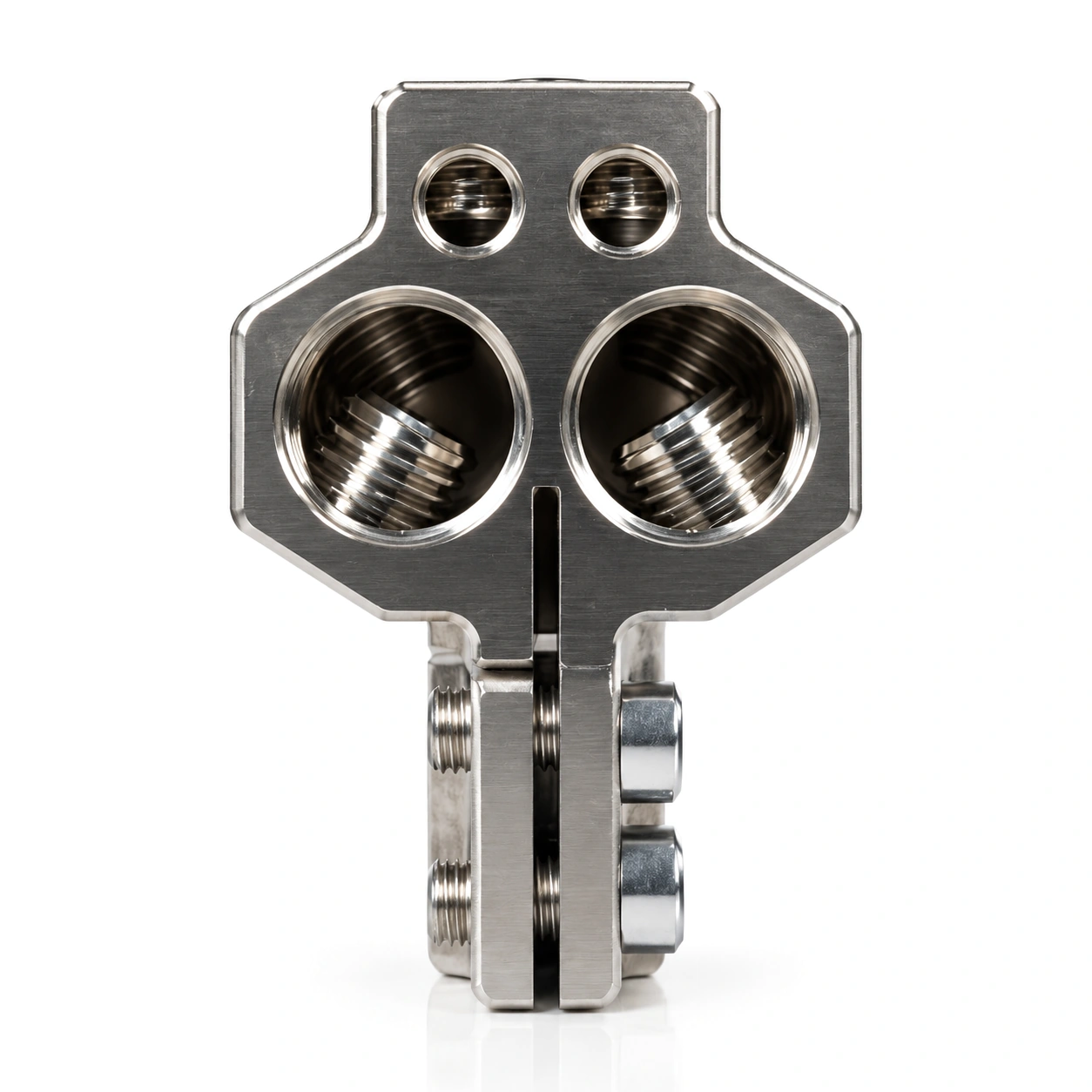 TOC-1, horizontalM12 / M20 / M30, 250 to 1000 A, 2 × 300 mm²
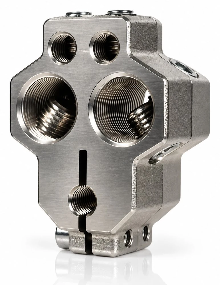 TOC-2, compactsame connection capacity, smaller footprint
No reviews!